Thursday, 5 March 2009

Instrument Flying.

How is your instrument flying?

My thanks to the author of this cartoon. It is one of my favourites!


Click here for a link to an aeroplane that I used to fly in my formative years in the RAF - the Whispering Giant. Here is a picture of the cockpit of the Bristol Britannia.

Wednesday, 4 February 2009

Point of No Return (PNR)

Similar to Point of Equal Time or Critical Point (CP), the Point of No Return is a straight forward equation easily resolved on your Dalton flight computer.
The Point of No return (PNR) depends on the fuel endurance time. After passing the Point of No Return the remaining fuel will not be sufficient for a return to the point of departure. The flight can only be continued to the destination or to an alternate airfield. It is, of course, also possible to calculate the Point of Safe Return based on the available fuel after deducting the required reserve.
The simple formula for PNR is:
T (PNR) = E X GS Home/[GS Out + GS Home] (Time formula)
Where: T (PNR) = Flying Time to PNR & E = Endurance.
The formula can also be transposed as:
T (PNR)/E = GS Home/[GS Out + GS Home]

Example: Endurance 6h30min. GS Out = 240kt. GS Home = 210kt.
On the flight computer:
Align 450 (240 + 210) on the inner scale with 210 (GS Home) on the outer scale. Read 182min outer scale against 390min (6h30min) on the inner scale.
Result: The PNR will be reached after a flight of 182min (3h02min). If the point is to be located geographically, determine the distance to the PNR by means of GS Out. In this example the distance to PNR will be 728nm. (182 mins @ 240kt.)

Equal Time Point (Critical Point)


It might be useful to briefly state here the formulae and Dalton flight computer solutions to the questions: What is the Critical Point? And what is the Point of No Return? The PNR will be discussed on the next blog page.
If, for example, engine trouble occurs during flight it is important for the pilot to know whether the airport of departure or the airport of destination can be reached sooner. For this the Point of Equal Time (P.E.T.) or Critical Point (C.P.) is determined. This is the point from which the continuation of the flight to the destination would require the same time as the return flight to the point of departure (or between any two points on your flight plan A & B).
The formula is T (P.E.T.) = TF X GS Home/[GS Out + GS Home] (Time formula)
Where:
T (P.E.T.) = Flying time to Point of Equal Time (or Critical Point).
TF = Time to fly from base (or A) to destination (or B) [Flight plan time or time A-B].
GS Out = Ground speed outbound.
GS Home = Ground speed inbound.
The distance from the point of departure (or A) to the point of Equal Time (Critical Point) is calculated by means of the following formula:
D (P.E.T.) = DZ X GS Home/[GS Out + GS Home] (Distance formula)
Where:
D (P.E.T.) = Distance from base (or A) to P.E.T.
DZ = Distance from base to destination (or A to B).
These equations may be transposed to the more convenient proportion form, as follows:
GS Home/[GS Out + GS Home] = T (P.E.T.)/TF or D (P.E.T.)/DZ 
On your flight computer simply align the sum of GS Out + GS Home on the inner scale with GS Home on the outer scale. Now read CP or Distance to CP on outer scale opposite Flight Plan time (or A-B time) and Distance departure to destination (or A-B distance) resp.
Example:
Distance A to B (DZ) = 920nm. GS Out = 240kt. GS Home = 210kt. Flight time A to B = 3h50min.
Required: Flying time to P.E.T. (C.P). & Distance to P.E.T. (C.P).
Intermediate calculation: GS Out + GS Home = 450kt.
On Flight Computer:
210 outer scale aligned with 450 inner scale. Read 107.5min outer scale opposite 230min (3h50min) innner scale & 430nm outer scale opposite 920nm inner scale.
Result: The P.E.T. (or C.P.) will be reached after a flying time of 107.5min. The distance flown will be 430nm.

Monday, 2 February 2009

What's AHEAD? Is this Aerofile Site Useful?

What's ahead? Is this AEROfile site useful? OR is it time to shut it down?

If there is any topic that YOU want published on this site then please say so via the comments facility. Use It Or Lose It!

Meanwhile, remember some of these Dead-Reckoning (DR) 'tips': See PPL Navigation Ex 18(X).

60/TAS x WS = Max Drift. (60 divided by True Air Speed multiplied by Met Office Windspeed = Maximum Drift in Degrees).

The 1/6ths rule:

0/6 of Max Drift for wind from 0-degrees OFF Track.

1/6 of Max Drift for wind from 10-degrees OFF Track.

2/6 of Max Drift for wind from 20-degrees Off Track.

3/6 of Max Drift for wind from 30-degrees Off Track. Etc up to 6/6 then Max Drift for 70, 80 and 90-degree beam wind.

HWC and TWC (Headwind & Tailwind Component): Use the 120 aide memoire:

Wind from 0, 10 & 20-degrees OFF Track: use 100% of Windspeed. (20+100=120 aide memoire)

Wind from 30-degrees OFF Track: use 90% of Windspeed. (30+90=120 aide memoire)

Wind from 40-degrees OFF Track: use 80% of Windspeed. (40+80=120 aide memoire)

Wind from 50-degrees OFF Track: use 60% of Windspeed. (50 use 60!)

Wind from 60-degrees OFF Track: use 50% of Windspeed. (60 use 50!)

Off-Track Correction:

Where, D1=Distance Flown. d1=Distance OFF track. D2=Distance to go to next waypoint.

T.E.1=Track Error in degrees after D1. T.E.1 correction (only) would result in the aircraft paralleling the reqired track to the next waypoint.

Therefore ADD T.E.2 to T.E.1 to fly direct to next waypoint.

60/D1 x d1 = T.E.1 and 60/D2 x d1 = T.E.2. ADD T.E.1 + T.E.2

Example:

Flying between waypoints A and B which are 120nm apart. After 40nm the aircraft is 4nm off track. What is the correction angle to fly to B?

D1=40. d1=4. D2=80.

60/40 x4=6-degrees (T.E1). 60/80 x4=3-degrees (T.E.2). Add 6+3=9-degrees correcton angle to fly to B from the OFF-Track position.

The author's other interest is motorbike touring. See here for the link.

Saturday, 3 January 2009

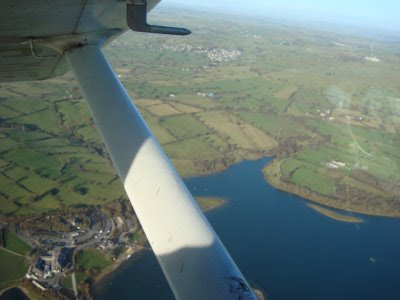
A few snapshots from a brief flight over Derbyshire.


Owslow Farm near Carsington.


Carsington Water

Chatsworth House

Over Haddon on the River Lathkill.

Another view of Over Haddon.

Sunday, 7 December 2008

The importance of LEADERSHIP.

Hello from the flight deck. Here is a question for you. Is good leadership important?

Answer: Of course it is. Good, effective leadership is vital in any organisation. If one is part of a team, that team has to have leadership. The leader (captain, chief pilot, chief instructor) must possess the qualities necessary to run a safe, motivated, dedicated team. The leader must set an example to his crew or his team. He should command respect. This respect has to be earned. Respect does not just 'happen' by virtue of appointment or badges. He has to be honest, be an effective communicator, a motivator and an example. His skill and knowledge, his manners and demeanor, should be beyond reproach. He should set 'the standard'. He should not court popularity, but should display those traits of character and personality that motivate his team members and those who report to him. The team should 'want' to work for him, and look up to him. Compassion and also a sense of humour are desirable traits. These characteristics do not only apply to the flight deck or cockpit of an aircraft, they are relevant in any environment or organisation. As far as flying training is concerned, learning how to 'pole' an aircraft is only one aspect of aviation. The development and demonstration of leadership qualities is vitally important and particularly relevant to Flying Training Organisations (FTOs) and Flying Schools - the crucibles for future professional pilots and private pilots.


But what do I know?

Saturday, 6 December 2008

PPL Ex 18 (xix): Navigation: "WIND UP" or "WIND DOWN" Method?

Please forgive me but I could not resist the temptation to put in this old picture of my Royal Air Force days in the 1960s flying Jet Provosts over the snowy North York Moors. I have been feeling nostalgic lately.

This may be a good time to remind all pilots that it is very EASY to access any page. Just go to the "green" Blog Archive index on the right. Click on the WHITE TRIANGULAR ARROW to open any month or year, and point and click on the underlined subject or PPL exercise that you want to look at >>>>>>>>>>>>>>>>>>>>>>

Today, in Navigation class, the question was asked, "Which method should I use? Wind UP or Wind DOWN on the Dalton computer?"

The answer is use either method, BUT know the characteristics (or quirks) of each method.

The "quirk" of the WIND DOWN method is that initially with TRACK at the INDEX, the TAS is placed on the centre line under the centre bore. We know that we cannot mix TAS with TRACK, because TAS goes with HEADING. Ground Speed (GS) goes with TRACK. But don't worry, it gets sorted out in the final movement of the plotting disc.

The "quirk" of the WIND UP method is that the "DRIFT LEFT" and "DRIFT RIGHT" stamped on the top of the fixed outer disc have to be read the opposite way round. Provided that this is remembered, I would favour the "WIND UP" method, because TAS is NOT placed on the centre line with TRACK. TAS is placed under the "X" at the end of the wind "vector" on the curved speed line. GS is now read under the centre bore.

The R.A.F. taught the "WIND DOWN" method. Why? Beause it is logical. On the "Wind Triangle" or "Triangle of Velocities" the aircraft is "downwind" of the HEADING VECTOR. The wind blows the aircraft from the HEADING to the TRACK. This whole methodology is explained in PPL Ex 18(i): NAVIGATION: The "Dalton" Dead Reckoning Computer. Nowadays I favour the WIND-UP method.

With BOTH methods we start with given information. This "given" information is: 1.)True Air Speed* (*See previous AEROfile entry for arriving at TAS). 2.) True Track (TRK T) and 3.) Wind Velocity (WV). Here is an example: TAS = 110. True Track = 050. W/V = 360/30

First the "WIND DOWN" method:

The wind direction (remember the wind is always FROM) is placed under the INDEX at the top of the instrument by rotating the plotting disc. The wind is 360/30. Rotate the disc until 360 (or "N") is under the "INDEX". Now, from the CENTRE BORE, measure "30" DOWNwards. Make a mark (a dot or a cross) at this point. Now rotate the disc to align the True Track 050 with the "INDEX" AND slide the disc to place the CENTRE BORE over the TAS 110. Observe the angle of the DRIFT LINE. It is 15 degrees on the RIGHT hand side of the plotting disc. (Note: The top right and left of the outer fixed disc states "DRIFT LEFT" and "DRIFT RIGHT" respectively). Here the drift is RIGHT therefore the heading is to the LEFT of the TRACK (the aircraft drifts towards the track!) Rotate the disc 15 degrees LESS than the TRACK value of 050 i.e. 035 under the INDEX. OBSERVE the DRIFT ANGLE NOW. It is now only 12 degrees. RE-ADJUST the figure under the INDEX to read 038. NOW THE DRIFT ANGLE (12 degrees) AGREES WITH THE DIFFERENCE BETWEEN THE TRACK AND THE HEADING (050 and 038 = 12). AND the plotting disc has "apples" and "apples" together and "pears" and "pears" together, i.e. TRACK with GS and HDG with TAS. The HDG and TAS have ended up on the centre-line. The Ground Speed (GS) is now read at the curved speed line under the "X" . It is 89. Bingo! We have True Heading (038) and Gound Speed (89).

Now the WIND -UP method:

The wind direction (remember the wind is always FROM) is placed under the INDEX at the top of the instrument by rotating the plotting disc. The wind is 360/30. Rotate the disc until 360 (or "N") is under the "INDEX". Now, from the CENTRE BORE, measure "30" UPwards. Make a mark (a dot or a cross) at this point.

Now rotate the disc to align the True Track 050 with the "INDEX" AND place the "X" of the wind vector over the TAS curved line at 110. Observe the angle of the DRIFT LINE. It is 12 degrees on the LEFT hand side of the plotting disc. (Note: The top left and right of the outer fixed disc states "DRIFT LEFT" and "DRIFT RIGHT" respectively). Here the drift is RIGHT therefore the heading is to the LEFT of the TRACK (the aircraft drifts towards the track!). THE "QUIRK" WITH THIS METHOD IS THAT ALTHOUGH THE INSTRUMENT HAS "DRIFT LEFT" STAMPED ON THE TOP (ON THE SIDE OF THE DRIFT LINE) WE HAVE TO REVERSE THIS. THE DRIFT IS ACTUALLY RIGHT! Other than this little quirk everything is fine and dandy. There is no adjusting to do. Simply subtract 12 degrees of drift from the TRUE TRACK of 050 = TRUE HEADING of 038 degrees, and read the Groundspeed under the centre bore = 89 knots. Bingo again!!